RMF Engineering further positions itself as a leader in district energy and is spotlighted throughout District Energy Magazine’s Autumn 2022 edition. Showcased in this issue is the RMF authored article discussing Cornell University’s North Campus improvements and its objective of reaching carbon neutrality, which was led by RMF’s talented Mechanical and Civil Engineers, Eric Chrencik and Stephen Pollard.
RMF’s Executive Vice President and IDEA’s liaison with the U.S. Green Building Council, Tim Griffin, also sits down with the firm’s Director of Sustainability, Martha Larson, in an intimate Q&A for this quarter’s LEED column on the decarbonization planning she led at Carleton College. Martha is also featured in the magazine’s “People on the Move” section!
Continue reading below to learn more about RMF’s involvement in Cornell’s North Campus improvements as it works to reach net zero.
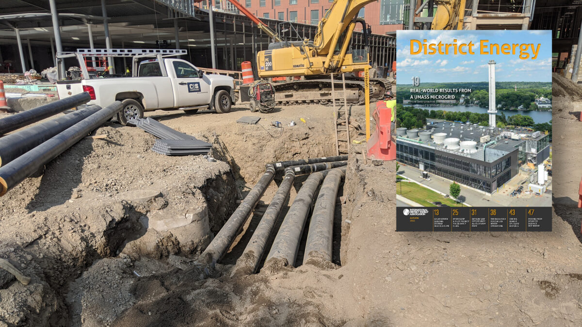
A previous version of the article below appeared in the Autumn 2022 issue of District Energy Magazine. To learn more about District Energy or read the full publication, please visit the website. Subscriptions are FREE.
Moving a university’s steam system toward lower-temperature district hot water: RMF Engineering leads North Campus improvements as Cornell works to reach net zero.
By Eric Chrencik
A multitude of considerations came into play when RMF Engineering began working with Cornell University to support the additionof five new buildings encompassed by its North Campus Residential Expansion.
Energy-efficient building design with an eye toward carbon emission reductions was paramount, and operations are showing peak heating and cooling loads from the new buildings well below expectations, suggesting that aggressive building-design standards offered a promising model for reducing the campus’s carbon footprint.
Additionally, a hybrid strategy of isolating the district hot water loop (180 F supply) from the buildings’
low-temperature hot water systems (130 F supply) allowed for a streamlined transition from the existing steam distribution system to lower-temperature technologies and for the future incorporation of alternatives such as heat pumps, waste heat systems, or ground and earth-source heat systems.
Cornell completed a student housing master plan in 2017 to address deferred maintenance and provide capacity growth. The first phase of that plan—the North Campus Residential Expansion Project—calls for a buildout of approximately 795,000 square feet, including several new residential buildings and dining facilities. The project was designed to aggressively conserve energy and water, and planners proposed that existing thermal utilities be extended to provide heating and cooling for the new buildings.
All heating and cooling utilities at Cornell are generated at central utility plants and distributed
via underground thermal distribution piping networks. Steam is generated at the Central Energy Plant (CEP). The CEP can provide up to 38 MW of electricity via two gas-fired steam turbines and 843,000 pph of steam via two heat recovery steam generators and five gas-fired auxiliary boilers.
Additionally, the CEP houses two electric centrifugal chillers and adjacent to the CEP is a thermal energy storage tank. Chilled water is primarily generated via the campus lake source cooling (LSC) plant. The LSC plant can provide up to 20,000 tons of cooling capacity at an average efficiency of 0.10 kw/ton.
The existing campus-wide steam distribution system consists of over 13 miles of steam piping, 12 miles of condensate piping and more than 160 vaults and manholes. Due to this extensive network, a simple solution for heating the North Campus would have been to extend steam to each building. However, the Cornell University Climate Action Plan, adopted in 2009 and revised three times since, outlined a campus goal for achieving carbon neutrality by 2035. In lieu of simply extending the existing steam distribution piping system to five new buildings, Cornell
set out a plan to provide low temperature hot water (180 F) to the North Campus buildings and begin eliminating steam.
For heating, project managers considered two options: natural gas-fired condensing boilers and electric The North Campus area had existing steam distribution and a small hot water distribution network. The original hot water system was constructed in 1971 of Transite piping to meet requirements at the time for a residential expansion of six buildings. This hot water system was replaced with FRP pipe in 1988 and upgraded again with Isoplus EN253 piping in 2013. This system couldn’t support expansion, however, so extending the existing 180 F hot water loop wasn’t an attractive option.
As for chilled water, the North Campus was fed from an existing distribution network insufficient for the proposed new cooling load, which would have resulted in pressure drops in the piping system that would be too great for the existing distribution pumps to handle.
Electrifying the new buildings to move closer to carbon neutrality was considered, but the cost would have been prohibitive because of infrastructure requirements. However, project managers saw steps that could be taken to move toward carbon neutrality while utilizing existing heating infrastructure.
Generally speaking, hybrid systems can be built around existing steam service to generate hot water for distribution, typically designed to operate at lower temperatures (180 F or less). The logic in this model is that the end-use buildings designed for lower hot water temperature operation open the door for current and future electrification options, avoiding the costly elimination of entire fossil-fuel district heating systems all at once.
After an evaluation of the existing steam and hot water systems, extensive life-cycle cost analysis and electrification/carbon-neutrality planning, an entirely new district hot-water loop with steam-to-hot-water heat exchangers was selected. A small district loop would be created to supply the five new buildings on the North Campus. This was seen as a preliminary investment in the transition to a low-carbon campus. Key considerations in the decision:
The existing district chilled water system at Cornell is three to four
times more efficient than a traditional chiller plant with electric centrifugal machines, so extending the LSC system and connecting buildings to the district loop was the preferred option. The main concern with connecting to the existing chilled water system was that there would not be sufficient capacity to serve North Campus buildings because the existing 14-inch HDPE chilled water mains routed under Beebe Lake.
To address this problem, Cornell’s chilled water hydraulic model was updated, and a strategy for boosting the chilled water system pressure was incorporated. This included the addition of two chilled water booster pumps in Chilled Water Plant 1 (CWP1). The plant originally housed chillers, but they had been removed. Existing 12-inch chilled water supply and return lines still passed through CWP1, however, and adding booster pumps to the plant allowed the North Campus buildings to be connected to the chilled water loop along with Balch Hall, which is being renovated and added to the CHW system. Additionally, the pumping layout was optimized to allow for a future booster chiller in
the plant.
The Mary Donlon steam-to-hot-water heat exchangers are at the heart of the system. Two styles were considered: vertical flooded and vertical non-flooded.
The vertical non-flooded spiral design heat exchanger was selected for its better temperature control, turn down, pricing and availability. A packaged system was procured with three heat exchangers (10,000 MBH each) to simplify the piping arrangement and ensure single source responsibility.
Though a condensate receiver is generally not required with vertical flooded heat exchangers that operate at high steam pressures, the vertical non-flooded exchangers selected operate at a maximum of 17 psig steam pressure. This meant a condensate receiver and pump set was required.
Vertical inline, horizontal split case and end-suction pumps were evaluated as potential hot water plant circulating pumps and chilled water booster pumps. Due to space constraints in the hot water plant mechanical room, vertical inline pumps were selected. For the CWP1 booster pumps, vertical inline pumps were chosen over horizontal split case pumps to ensure that free space in CWP1 was maintained. Horizontal split case pumps also limited clearance and accessibility. All pumps were provided with variable frequency drives, which modulate based on differential pressure set points for various buildings on the North Campus loops.
N253 and PEX piping were evaluated for use in the hot water distribution system. Pre-insulated, double-wall steel was eliminated because Cornell already had experience and good success with thin wall piping systems. The 180 F hot water supply temperature pushed the upper limits of the PEX piping system. Additionally, pre-insulated, thin wall, EN253 piping with integral leak detection ultimately led to the elimination of PEX from consideration. The final hot water district consisted of 4-inch and 6-inch EN253 thin wall steel piping. The distribution piping layout is designed so that anchors and expansion loops are not required.
For chilled water distribution, pre-insulated HDPE was selected for its cost, familiarity and long life expectancy.
Since completion of the project described in this article, a second ETS has been put into service, converting five additional buildings to hot water, with two additional projects currently in design. The new design standards have resulted in increased occupant comfort, energy reductions, reduced distribution thermal losses and longer-lasting, safer distribution infrastructure.
Good project management came into play by way of a strategy that divided the work across two sites.
Site 1 was completed for fall 2021 move-in, and the new dining hall was in service when students returned in January 2022. Site 2 was completed later in the year for August move-in.